PCSCHEMATIC Automation is a tailored CAD program for electrical documentation. The program keeps track of all the practical details and allows you to focus on your projects. Automation has an intuitive workflow that enables you to start your tasks immediately.
Automation has an intuitive workflow, which enables you to start your tasks immediately – well supported by the free educational videos on PCSCHEMATIC’s YouTube channel and a wide range of courses offered.
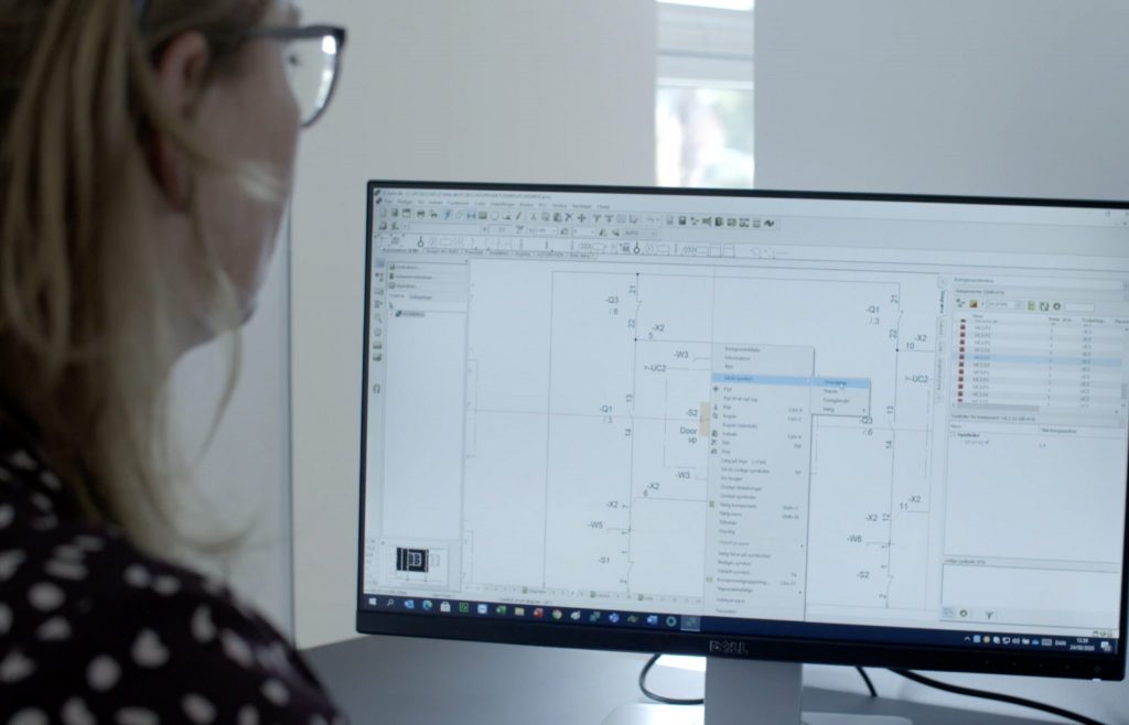
The program handles reference designations intelligently according to IEC/ISO 81346, and contains symbols for automation, PLC, topology/bus connections, one-line diagrams, pneumatics/hydraulics, and house installation. While you focus on a drawing correctly, the program automatically ensures that everyone updates all lists.
All variants of the program have full functionality and contain all available modules.
With Automation you achieve high efficiency as you only have to do things once in one place:
Once you have made a partial drawing, you can drag it into all subsequent projects and when you have created partial projects or entire projects, they can be dragged in in the same way. This intelligent reuse of data makes you more efficient, while at the same time, you create uniform documentation that follows the company’s or customer’s guidelines.
Automation has a component-based workflow:
Automation contains an advanced database and an associated online Component Portal
Electrical and mechanical symbols are attached to all components
If a component is selected in the portal, all its associated data is automatically obtained
Component guide for quickly creating your own components with associated symbols and data
Correct documentation offers unimaginable possibilities for the output of lists and graphic plans
All types of lists are included
Lists are updated automatically – based on the data linked to the components of the project
Lists at page, chapter & project level
Export all lists for use in production – wire numbers, markings, I/O lists, wire cutters, etc.
When you choose PC | Automation, all the functions are available, regardless of which variant you want. All variants of the program have full functionality and contain all available modules.
All functions mentioned below are available in all variants of Automation. They are available in Automation Advanced, Smart, Flex and in the free Automation 40.You don’t need to purchase the expensive variants of the software to get all functionality you need and you can always upscale to a bigger variant
Project oriented: All parts of a project gathered as pages in a single file – including diagrams, mechanical pages, lists, tables of contents, chapter dividers etc.
Enhanced Explorer window: For easy navigation between projects and project pages, and for finding symbols etc. in project pages
Net navigator for easy navigation through electrical potentials
Cross references are created and updated automatically for all types of components: Click and jump between the symbols for a component, or click in lists and jump directly to the component
Object Lister for overview over all objects in the documentation – and for editing their attached texts/data. (Texts can also be edited by clicking on the individual texts in the project pages)
Show available window: Easy access to all components with unused symbols/functions
Creation and handling of reference designations at component, area, page and project level (function, location and product aspects) – according to IEC 81346, KKS or user defined standards
Reference designations handled intelligently when changing, copying and merging pages and projects
Project, page and list templates – just drag them into your projects
Component wizard for quick and effective creation of own components with attached symbols
Unique timesaving database workflow: Symbol pickmenus for all multi-function components in the database – just click and place the symbols in the diagrams and article data are attached automatically
Advanced copying: All symbols and their reference designations are renamed intelligently – e.g. when copying symbols and areas, or when inserting subdrawings, subprojects and projects. Attached article data are included when copying
Rename symbols and Insert name at project level
Automatic load of mechanical symbols for the components used – handled by the database
Automatic list update: Of tables of contents, parts lists (BOM), component lists, terminal lists, cable lists, connection lists, labels and PLC lists. Any of these lists can be defined freely by you
Excel/XML/text files can be exported for all of the mentioned list types
Export of wire numbers
Drawing headers for any type of project page can be defined freely – and can be replaced on project level
Automatic generation of graphical terminal, cable and connection plans
Flexible sharing of net licenses and licensea borrowing
Administrator control
Automation – always updated
PCSCHEMATIC Automation Maintenance Agreement includes software updates and upgrades. I addition you also get access to the Component portal and our unique personal support.